Design & Construction of 1/2-Wave Tesla Coil |
William C. Wysock |
Tesla Technology Research |
2527 Treelane Avenue |
Monrovia, CA 91016 |
Abstract
In this paper, the design and construction of a 1/2 Lambda Tesla Coil are discussed. The most significant feature of this system is the primary resonant tank circuit in a series fed configuration. The system consists of two identical 1/4-Lambda Tesla resonators which are electrically phased to produce opposite sign oscillations between the respective high voltage terminals. The first public demonstration of this system was in an indoor auditorium at Cheyenne Mountain High School in Colorado Springs, Colorado, between July 21 to 25, 1992, to coincide with the occasion of the Fifth Biannual International Tesla Society Symposium. Observations from the results obtained with this prototype system are noted.
System Design
The Model 12 Tesla Coil System consists of two each 1/2-wavelength Tesla transformers, arranged to have each primary coil fed in series. One-inch diameter copper tubes, 10 feet in length, are connected between standoff insulators in a bifilar arrangement, to lower self-inductance and increase capacity. There are four separate 10-foot long links for this connection. In the middle of one side of the primary tank circuit is placed the oscillation capacitor bank. As deployed in the Shaw Auditorium at Cheyenne Mountain High School, the total capacity used was 0.125 mfd.
The power supply transformer was connected in parallel across the capacitor bank. Opposite the capacitor bank on the return side of the tank circuit was a synchronous rotary spark gap. This gap has been specially modified so that it has both adjustable dwell angle and duration. Further, these two characteristics may be independently adjusted from each other or ganged together.
At the ends of the 10-foot transmission line busses are four flexible connecting cables made from 250 MCM welding cable stock. These connect to 1" x 14" x 1/4" copper buss terminals, which in turn strap on to the 4" wide copper ribbon primary inductances. The base platforms upon which are wound these Tesla primary inductances, have access cutouts between their respective copper ribbon phenolic support blocks, thus allowing for any arrangement of inductance connection. Each primary inductance consists of5 turns, arranged in an Archimedian spiral, on 1" turns spacing.
The two Tesla secondary coils are identical, but wound in opposite directions. Each coil form is made from phenolic tube stock. Provisions for additional insulation or dielectric strength have been provided for by the interior air space of each tube. The windings on these tubes consists of 350 turns, space-wound at the rate of six turns per inch. The wire stock consists of # 16 AWG stranded, PVC insulated wire. Each winding is 2,424-feet in length. Each winding assembly is painted with several coats of electrical gylpt insulating varnish.
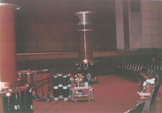 Model 12 Tesla coil system. Distance
between coils approximatly 40 feet. Maximum arc length (this setup) approx. 38 feet. (From
International Tesla Society "Zap Show", July 1992.)
Model 12 Tesla coil system. Distance
between coils approximatly 40 feet. Maximum arc length (this setup) approx. 38 feet. (From
International Tesla Society "Zap Show", July 1992.)
Each secondary coil is terminated with three separate hollow aluminum toroid discharge electrodes. The first acts as a final turn of the coil, and serves to reduce electrical stresses at the top of each winding. The second and third toroids serve to add needed total terminal capacity, and are sized to distribute the high voltage charge over an effective area much larger then the size of the individual toroids themselves. Adjustable brass rods are provided on the side of each upper toroid assembly, to direct the discharge from each coil to the opposite side.
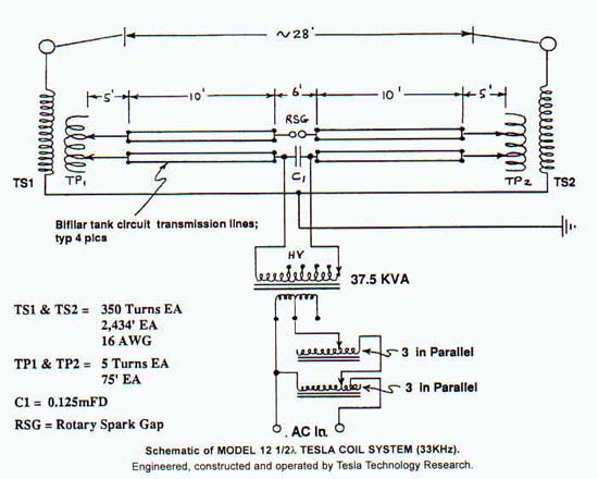
The power supply for the Model 12 Tesla Coil System consists of a 37.5 Kva utility pole transformer, with the low voltage terminals set for either 240 or 480 volts, and the higher voltage terminals set for 36.4 KV. Power is fed to this transformer from two triple-stack autotransformers, the first stack being wired for variable voltage control, the second connected in series with the output of the first, for current control and power factor correction. At the Cheyenne Mountain High School, the power feed was from two legs or phases of a 208 volt 3-phase line, with a 125 amp power breaker being used as a master switch. The actual measured voltage across any two of this 3 phase line measured 201 volts AC RMS.
The load voltage applied to the Model 12 coil in this auditorium was limited to 150 volts, which is about 60% of full system operating capacity. This was due to the fact that as large as this auditorium was, it nevertheless was still not large enough to allow for safe placement of the two Tesla Coils at their maximum design distance of 40 feet. The input power was thus limited to 150 volts, in order to prevent the possibility of stray arcs from the two secondary coils to their adjacent walls, audience seating areas, etc. Power drawn from this line was about 120 amps, at the settings used.
Ground plane capacitance effects on a double coil system of this size is a very significant factor. During initial tuning, it was discovered that there was much greater capacitive loading on the left hand coil in the auditorium, than on the right side. This was due to the fact that behind the left hand wall area were located many electrical conduits, breakerboxes, etc. -- all of which added to that coil's parallel electrostatic capacitance. The effect on the Tesla primary coil tuning, was finally corrected for this condition by having the left hand primary inductance set at exactly 2.0 turns, while the right side was set for exactly 1.75 turns. The difference in the two primary coils was only 27 inches in length of the 4-inch wide copper ribbon! This gave some indication of the "M" (mutual coupling coefficient) of the system!
As originally tested at Monrovia, California, the week before the Symposium, both coils resonated together and equally at 1.875 turns. As originally setup in the auditorium, these settings provided a 17'+ corona discharge from the right hand coil, while the left hand coil only gave about a 20" corona! By offsetting the two primaries boy only a 27" length of ribbon, both coils gave a 17'+ discharge. It should be noted here that the physical length of each primary inductance is 75 feet, and the total primary resonant tank circuit is 216 feet.
System Performance
The demonstrations at the Cheyenne Mountain High School in Colorado Springs marked the first public demonstration of this coil system. No attempt had been made to quantify system performance prior to shipping the equipment to Colorado due to lack of time. The system was initially setup in Monrovia, to verify system capability only. AS setup in Colorado, this coil system resonated at approximately 33KHz in 1/2 Lambda configuration. The rotary gap gave satisfactory performance and was run at a pulse repetition rate (PRF) of 240 pulses per second, (PPS). Each oscillatory pulse duration was limited to about 40 microseconds. The primary resonant tank circuit carried peak currents in excess of 10KA. A resonant rise on the AC mains was observed to be on the order of 50 volts, (this voltage was out of phase with respect to the charging load voltage of 150 volts.)
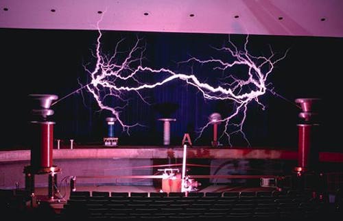 The Model 12 1/2 Lambda Coil System
(33KHz) in operation inside Shaw Auditorium at the Cheyenne Mountain High School, Colorado
Springs. Photo: C.J. Nagy
The straight line distance between the corona
discharge rods on the two Tesla secondary coils was set at about 28 feet, however,
considering the tenuous path taken by most of the power arcs between the two coils, the
actual arc path length may have been on the order of about 36 feet.
The Model 12 1/2 Lambda Coil System
(33KHz) in operation inside Shaw Auditorium at the Cheyenne Mountain High School, Colorado
Springs. Photo: C.J. Nagy
The straight line distance between the corona
discharge rods on the two Tesla secondary coils was set at about 28 feet, however,
considering the tenuous path taken by most of the power arcs between the two coils, the
actual arc path length may have been on the order of about 36 feet.
Careful attention had to be paid to the grounding arrangement of the input to the two secondary coils. This was accomplished by having each ground leg from each secondary coil be of exactly the same physical length and path, joining a common point, then being connected to a good electrical RF ground reference, (the water main valve for the fire extinguisher system of the auditorium was utilized as the master grounding point.)
The sound pressure levels of the discharges from this Tesla Coil system were measured with the auditorium empty, using a real time spectrum analyzer with an "A" weighted scale. Peak amplitude under 1 KHz measured 109 dB SPL in the middle row seating area.
A careful review of the available literature was made over a 15 year period for any Tesla Coil systems similar to the one built and exhibited. Whereas there were a number of 1/2 Lambda or wavelength coils built and described in various historical periodicals, none were found that followed the design criteria of this system. We believe that this Model 12 Tesla Coil system is the largest of its design ever built and publicly demonstrated. __WCW
© 1992 International Tesla Society, Inc - page 51 - 54