http://www.electrotherapymuseum.com
(C) Jeff Behary 2007
The Turn Of The Century
Electrotherapy Museum
http://www.electrotherapymuseum.com
(C) Jeff Behary 2007
Medical Electrology and Radiology
Voltage Step-up Transformers
with Magnetomotive Switch, S.G.D.G. patented
Induction coil Or Step-up transformer
The increasing use of induction coil for the production of high voltage required in radiology and in high frequency, led us to embark upon the construction of these coils by bringing some improvements based on/withdrawn from experience and common practice. These coils, built with great care, are guaranteed “non-puncturable” (i.e. can not be punctured) thanks to a rational calculation of the insulators, which has been built exactly proportionate to the voltage they have to bear.
Primary – The primary (winding) is constituted by a nucleus composed of soft metal leaf, special, very thin, reducing to the minimum the loss in a Foucault circuit configuration. This nucleus is very big, so that it never reaches complete saturation. The loss by hysteresis is therefore insignificant. On this nucleus, is located the primary winding. It contains a number of wire loops/turns that is variable with the source of voltage. In the coils destined to work with sources of different voltage, such as the portable coils, or when it is necessary to vary the self-induction depending on the needs, the primary winding is divided into sections which can be successively added or removed from the circuit thanks to a switch. The coupling of the different sections is carried on under voltage/power.
We have brought a very particular care to the choice of the insulator dividing the primary from the secondary winding, because it was the weak point of all induction coils. Apart from the ebonite tube, which in all induction coils, surrounds the primary, a certain gap has been spared/reserved around this tube and is filled with a composition assuring perfect isolation.
Secondary – The induced or the secondary (winding) is a system with multiple protective layers. It is composed of a big number of “galettes /disks” each containing only a small number of turns, and isolated from one another by slices made of a special insulating cardboard, which completely prevents discharge from one disk/galette to another. These latter are coupled, and are positioned in the magnetic field so that they may sustain the maximum induction possible. Everything is immersed in an insulating composition, insensitive to temperature fluctuations, and preventing any internal discharge.
The antennas, separated by a distance equal to the length of the catalogued filaments/flicker (this length is always inferior to the real maximum length), are built so that they can directly be fitted (on demand) to our “spintermeter” - a device which can be disassembled. This makes it more practical and reduces the bulkiness while simplifying the wiring.
Page 2:
Our induction coils are locked in a mahogany box whose base contains the capacitor. Its capacity is accurately set to provide a maximum yield with our magnetomotive switch (described further), and with which all our coils can be fitted.
This switch is fixed on the base, and can be removed and disassembled without removing any of the connections.
In some cases, when necessary, the capacitor is built with a variable capacity, and can be tuned/adjusted by means of a keyed-switch allowing the introduction of a variable number of blades, which will have the effect of fluctuating the capacity from 1 to 30 or more, depending on the induction coils.
In summary, the simple and robust construction of our induction coils allows maximum yield with minimum power consumption, whilst at the same time, maximum durability and performance.
The switch
The induction coils built in order to increase electric voltage, so far worked with rotary independent mercury switches, being activated by means of an engine.
This new switch, built upon Dr. Beclere’s instructions, can be adapted to all induction coils powered by a DC source (direct current), whatever the voltage.
This new switch presents several important advantages over the turbine switches that predate it.
In the standard model, which has been especially designed for coils with accessible magnetic nucleus, the engine activating the switch has been removed and replaced by an iron revolving “door” with 2 or 4 branches, fixed on the coil axis, and facing one end of the magnetic nucleus. We describe the mechanisms further in the text.
The major innovation brought to the switch is the use, as a dielectric, of an appropriate gas, Hydrogen, Acetylene or lighting gas, having the property to completely prevent the mercury emulsion, and has allowed reducing the charge/weight to about 400 grams.
In summary, this switch has not only a simplified construction and operation procedure, it also presents the advantage of not requiring any cleaning, since there is no mercury emulsion. Furthermore, its weight and its volume have been significantly reduced, which allows its advantageous use in portable devices.
Description
This switch is a kind of rotating jet and presents the particularity of not requiring any engine when it is combined with an induction coil fitted with a magnetic nucleus accessible by one end. The construction process is thus simplified and the robustness is thus greater.
The engine system is only composed of an iron revolving “door” with as many branches as there are contact keys on the switch, usually 2 or 4. This revolving “door”, fixed on the upper end of the “tree” bearing the centrifugal turbine, is exactly leveled up to the magnetic mucleus, right in its axis, with the tips of the branches located a few millimeters away from the nucleus.
The centrifugal turbine, fixed on the lower end of the “tree” and immersed in the mercury, is a steel cylinder pierced with a Z-shaped hole, in order to allow the passage of the mercury jet, required for a good connection. When this part spins, the mercury is expulsed by centrifugal force and is projected through the upper opening/orifice onto the contact keys.
Page 3:
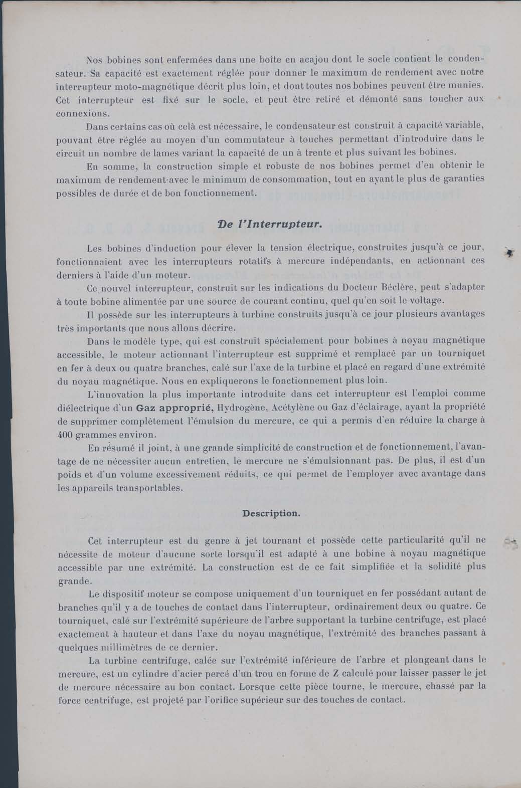
The metallic rim bearing these keys is fixed underneath the lid, made of an insulating material, and is linked by a contact blade to a “moving” stem in a fiber socket, thus isolating it from the “container”, and communicating by friction to a terminal connected to a “cable line”.
The pallets are in number of 2 or 4, depending on the voltage of the source.
The “container” containing the mercury, is made of cast iron, and is divided at its lower section by fins preventing any turning motion during the rotation of the turbine.
It makes contact through a copper rim which encircle its base tightly, and in which it rotate freely. This rim, which is fixed at the base of the coil, bears the terminal which is connected to the second “cable line/wire line”.
A tuning lever, screwed onto the “container”, allows its free movement in one direction or the other.
The gap section above the mercury, is filled up with an appropriate gas, Hydrogen, Acetylene, lighting gas, etc…in which occurs the break/rupture. The use of a dielectric gas has for advantage not to create any mercury emulsion, from which we have thus reduced the charge to the strict minimum (400 grams), which is equivalent to about 14 times less than the charge in similar models using dielectric liquids/solutions.
Charge.
To operate the switch, simply unscrew the 4 “buttons/screws”, remove the upper section, and fill up with mercury up to the level of the “container” fins.
After sealing the switch by firmly tightening the “buttons/screws”, plug one of the valves on the gas line and open the other valve until all the air in the “container” has been removed, and then close up the drain valve. This operation/step is essential to prevent the formation of an explosive mixture.
If no gas source is accessible, simply pump up a “balloon” that will be fitted to the valve, and proceed as described above, or simply add a few drops of mineral oil, or petroleum ether, and operate the switch within the first minute, valves opened, since vapors from hydrocarbons can act as/create a very appropriate gas.
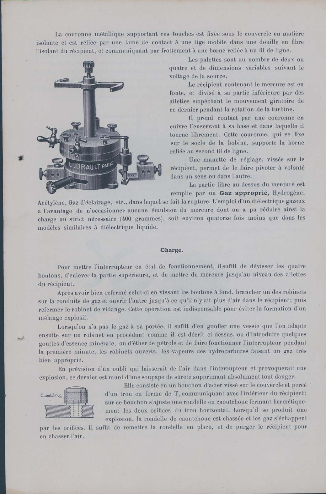
In case of omission, resulting in the presence of air in the switch and likely to cause an explosion, the switch is fitted up with a safety-valve preventing any danger/risks. It consists in a cast-iron plug/cap screwed on the lid and punched with a T-shaped hole, which communicates with the interior of the “container”; on this plug/cap, there is a rubber disk which renders the 2 orifices of the horizontal hole airtight. When an explosion occurs, the rubber disk is expelled and the gases escape through the orifices. To reset, simply reposition the rubber disk and purge the “container” of air.
Page 4:
Assembly:
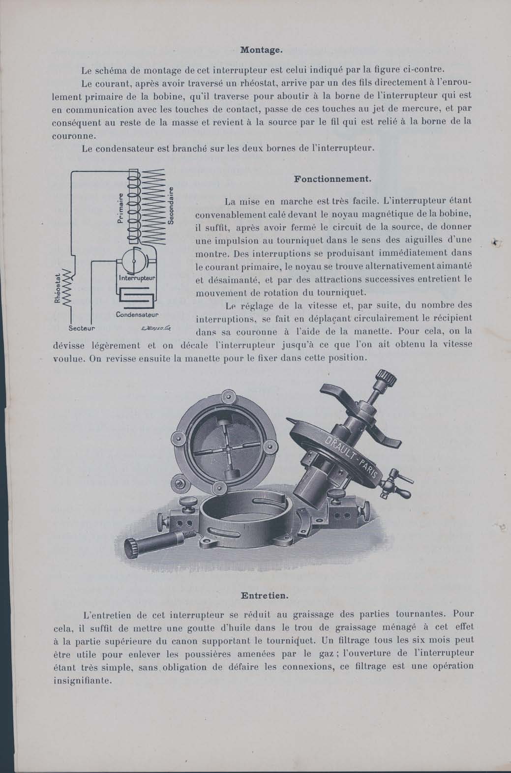
The assembly scheme of the switch is shown in the opposite figure.
After going through the rheostat, the current directly reaches the primary winding of the induction coil, crosses it, and ends up at the switch terminal, which is connected to the key contact. It then goes from the key contact to the mercury jet and, therefore, the rest of the mass, and comes back to the source via the wire connected to the rim terminal.
The capacitor is plugged onto the 2 switch “terminals/pins”.
Operation:
The actuation is very easy. With the switch properly fixed in front of the nucleus coil, simply close the source circuit, and give a pulse to the revolving “door” clock-wise.
Interruptions will occur in the primary current, the
nucleus will be alternatively
”magnatized” and “dismagnatized”, which will create attractive forces, and will
sustain the rotary motion of the revolving “door”.
The control of the speed and the number of interruptions is set by circularly shifting/moving the “container” within its rim, by means of the lever. To achieve this, slightly unscrew the lever and shift the switch to achieve the target speed. Then, tighten the lever to keep it in place.
FIGURE
Care/Maintenance
Care of this switch only required greasing of the rotating parts. To achieve this, simply apply a drop of oil in the greasing hole built in the upper section/compartment of the rod bearing the revolving “door”. One filtration every 6 months can be useful to remove dust brought in by the gas; since the dissembling of the switch is very easy/simple, and does not require removal of any wiring, this filtration does not represent a difficult procedure.
Page 5:
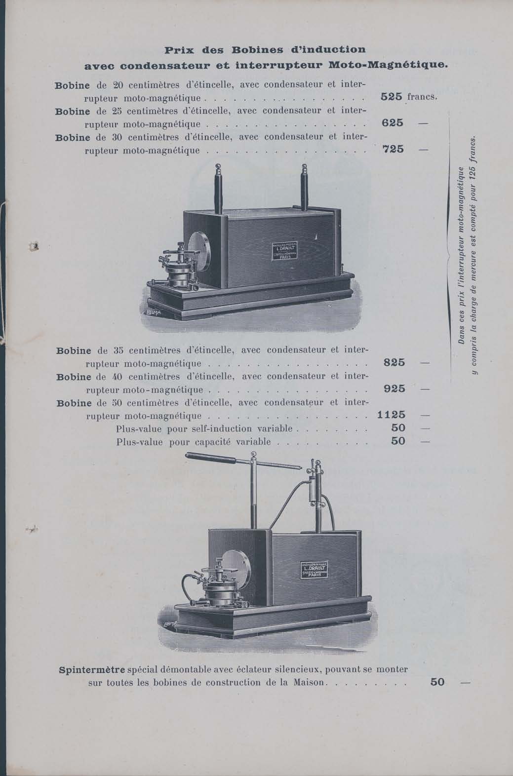
Price of induction coils with capacitor and magnetomotive switch.
Coil with a 20 cm-filament, with capacitor and magnetomotive switch ……….525 francs
Coil with a 25 cm-filament, with capacitor and magnetomotive switch ……….625 francs
Coil with a 30 cm-filament, with capacitor and magnetomotive switch ……….725 francs
FIGURE
Coil with a 35 cm-filament, with capacitor and magnetomotive switch ……….825 francs
Coil with a 40 cm- filament, with capacitor and magnetomotive switch …….925 francs
Coil with a 50 cm- filament, with capacitor and magnetomotive switch …….1125 francs
Supplementary fee for variable self-induction……………….50 francs
Supplementary fee for variable capacity…………………….50 francs
FIGURE
Fig. Legend: Special spintermetre, can be disassembled, fitted with a silent “burst”, and can be fitted to all coils manufactured by the company………………………50 francs
Page 6:
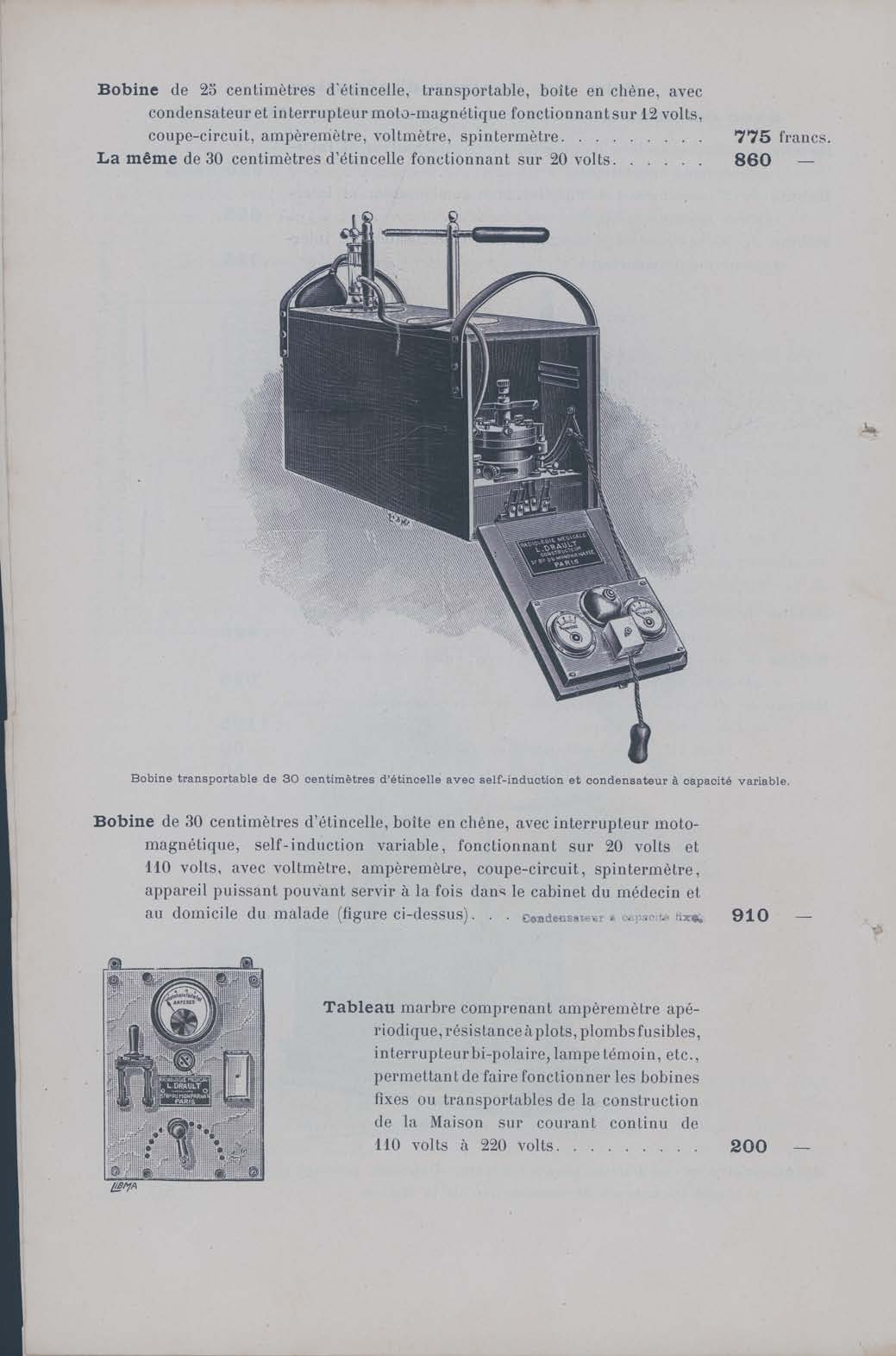
Coil with a 25 cm- filament, portable, oak outer box, with capacitor and magnetomotive switch, can be powered by 12 Volts, “cut-circuit”, voltmeter, ammeter …..775 francs
Same coil with a 30 cm- filament, can be powered by 20 volts………..……..860 francs
FIGURE
Coil with a 25 cm- filament, portable, oak outer box, with capacitor and magnetomotive switch, can be powered by 12 Volts, “cut-circuit”, voltmeter, ammeter. This powerful device can be used either in a surgery or in the patient’s home ……….…..910 francs
Marble board comprising “non-periodic” ammeter, plug resistance, fuses, bipolar switch, signal lamp, etc., allowing operation of fixed or portable coils powered by a 110Volts to 220 Volts DC (direct current) …………………………………………………200 francs
Page 7:
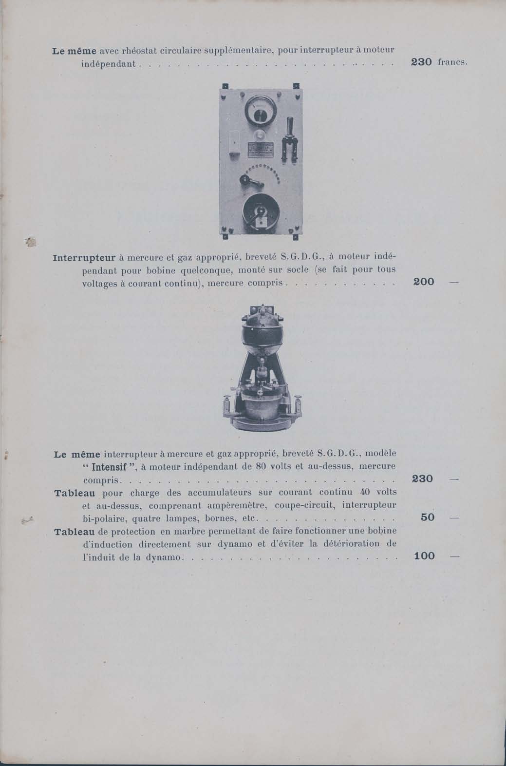
Same marble board with supplementary circular rheostat, for switch with independent engine……………………………………………………………………230 francs
Mercury Switch with appropriate gas, S.G.D.G. patented, with independent engine for any type of coil, fitted on a base (is done for all DC voltage), mercury is included…200 francs
Same mercury switch with appropriate gas, SGDG patented, “Intensive” model, with independent engine of 80 volts or more, mercury is included………………..230 francs
Board for charging accumulators/batteries on 40volts DC or more, comprising ammeter, “cut-circuit”, bipolar switch, 4 lamps/bulbs, terminals, etc……………………50 francs
Marble protection board allowing the operation of an induction coil directly on dynamo, thus avoiding deterioration of the dynamo rod/core…………………………….100 francs